
PC-Based MX100
For test applications with data logging requirements, the MX100 scales from four to 1200 channels. It streams, records, displays, and reports with no programming required.
When combined with Yokogawa's turnkey PC software, the MX100's multi-channel capability and high isolation voltage offers the ultimate in measurement power.
Description:
For test applications with data logging requirements, the MX100 scales from four to 1200 channels. It streams, records, displays, and reports with no programming required.
When combined with Yokogawa's turnkey PC software, the MX100's multi-channel capability and high isolation voltage offers the ultimate in measurement power.
Multi-Channel Capability, High Isoration Voltage
Shortest measurement interval of 10 ms (high-speed measurement of 10 ms on 24 channels or 100 ms on 60 channels is possible).
Possible to acquire data from up to 1,200 channels (when using Yokogawa's proprietary software).
Reinforced insulation between the input terminal and the case handles 3700 Vrms for one minute, or 600 Vrms/VDC continuous.
Multi-Interval Measurement
Mixed use of three types of measurement intervals is enabled within the system (measurement intervals are set for each module).
Easier to Use
Flexible System Configuration
By configuring modules, a system can be built or modified to utilize 4 to 1,200 channels, and measurement intervals of 10 ms to 60 s.
Versatile PC-Based Software Options
Software developed by Yokogawa, an API, and a LabVIEW driver are available.
Easy Software Setup
PC software developed by Yokogawa automatically identifies any connected MX100s.
The table below provides reference information on the maximum number of measurable channels in relevant measurement intervals (when using Yokogawa's proprietary software):
| Measurement interval | Maximum number of measurable channels | Measurable objects | PC software | Number of necessary modules (example) | |||
|---|---|---|---|---|---|---|---|
| MX100 Standard software | MXLOGGER | Main Module (MX100) | Four-channel High-speed Universal Input Module (MX110-UNV-H04) | Ten-channel Medium-speed Universal Input Module (MX110-UNV-M10) | |||
| 10 ms | 24 channels | DCV/DI | √ | √ | 1 | 6 | — |
| 50 ms | 24 channels | DCV/TC/RTD/DI | √ | √ | 1 | 6 | — |
| 50 ms | 120 channels | DCV/TC/RTD/DI | — | √ | 5 | 30 | — |
| 100 ms | 60 channels | DCV/TC/RTD/DI | √ | √ | 1 | 0 | 6 |
| 200 ms | 500 channels | DCV/TC/RTD/DI | — | √ | 9 | 0 | 50 |
| 500 ms | 600 channels | DCV/TC/RTD/DI | — | √ | 10 | 0 | 60 |
| 1000 ms | 1200 channels | DCV/TC/RTD/DI | — | √ | 20 | 0 | 120 |
√ measurement that support is possible
— measurement that support is not possible
The relationship between measurement intervals and the number of channels largely depends on the performance of the PC. The actual performance may differ from that shown in the table.
CPU: Pentium 4 3.2 GHz; Memory: 1 GB; OS: Windows 2000; Hard disk: 160 GB
Communication interface: Ethernet 100Base-TX
Multi-Interval Measurement
Three types of measurement intervals can be used in a single system in various combinations. Measurement intervals are specified for each module. It is also possible to set different types of input modules to the same measurement interval or to set the same type of input modules to different measurement intervals. Twelve measurement intervals are available as userselectable options: 10 ms, 50 ms, 100 ms, 200 ms, 500 ms, 1 s, 2 s, 5 s, 10 s, 20 s, 30 s and 60 s. Please note, however, that measurement intervals of 10/50 ms cannot be set to the Medium-speed Universal Input Module (MX110-UNV-M10).
Multi-interval systems can be flexibly built for each module as shown in the figure below. Three colors  are used to indicate the three types of measurement intervals.

Examples of Setting Measurement Intervals

Monitor Window Using Yokogawa's Proprietary PC Software
The window shows measurement values by measurement intervals. Measurement can be performed while confirming rapidly-changing signals and slowly-changing signals simultaneously.
A: Measurement of sine waves at 0.5 Hz with a measurement interval of 100 ms
B: Measurement of sine waves at 8 Hz with a measurement interval of 10 ms
C: Measurement of sine waves at 1 Hz with a measurement interval of 50 ms
One MX unit enables data acquisition on up to 24 channels at a measurement interval of 10 ms, or up to 60 channels at a measurement interval of 100 ms (six modules installed in both cases).
Input signal
DC voltageThermocuple, RTD, Digital input (mixed input possible)
Output signal
Digital output
Setting up the System
The MX and PC are connected via a hub and a straight Ethernet cable.
Alternatively, they can be connected using a cross cable alone, without using the hub.
PC Software
In a one-to-one connection, the MX100 standard software included with the main module facilitates easy building of data acquisition environments.
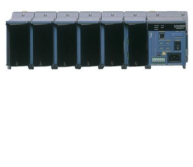
One MX unit consists of a combination of a main module, input/output modules, and a base plate. This configuration centers on the main module.
Connection between multiple MX units and a single PC
 |
| Example of a system with multiple MX units |
Setting up the System
The MX units and the PC are connected by means of a hub and straight Ethernet cables.
PC Software
Acquisition of data from multiple MX units is well-supported by Yokogawa's software "MXLOGGER" (optional). MXLOGGER enables data acquisitions of up to 20 MX units (one unit has inputs of up to 60 channels, or 1,200 channels on 20 units).
Please note that the shortest measurement interval of MXLOGGER depends on the system's total number of channels and the PC's performance.
If users wish to create their own data acquisition software, there is no limit to the number of MX units that can be integrated with a single PC software element. Please note, however, that if conditions with heavy loads (such as short measurement intervals with many units) are set to the PC and its software, data will not be acquired in time and some data may be lost.
| Name | Model | No. of channels | Shortest measurement interval | Description |
|---|---|---|---|---|
30 ch general purpose input module with 500 ms scan speed  | MX110-VTDL30 | 30 | 500 ms | Clamp terminal, DCV/TC/DI |
| MX110-VTDL30/H3 | 30 | 500 ms | M3 screw terminal, DCV/TC/DI |

| Name | Model | No. of channels | Shortest measurement interval | Description |
|---|---|---|---|---|
| Universal Input Modules | MX110-UNV-H04 | 4 | 10 ms | DC voltage, thermocouple, 3-wire RTD, DI (non-voltage contact, Level (5 V logic)). Mixed input allowed. |
| MX110-UNV-M10 | 10 | 100 ms | DC voltage, thermocouple, 3-wire RTD, DI (non-voltage contact, Level (5 V logic)). Mixed input allowed. | |
| 4-Wire RTD and Resistance Input Module | MX110-V4R-M06 | 6 | 100 ms | DC voltage, 4-wire RTD, 4-wire resistance, DI (non-voltage contact, Level (5 V logic)). Mixed input allowed. |
| Strain Input Modules | MX112-B12-M04 | 4 | 100 ms | Built-in bridge resistance of 120 ohm |
| MX112-B35-M04 | Built-in bridge resistance of 350 ohm | |||
| MX112-NDI-M04 | For connection with an external bridge head and strain gauge type sensor (NDIS connector)) | |||
| 5 V Digital Input Module | MX115-D05-H10 | 10 | 10 ms | Non-voltage contact, open collector, and Level (5 V logic). Mixed input allowed. |
| 24 V Digital Input Module | MX115-D24-H10 | 10 | 10 ms | Level (24 V logic), Vth = 12 V |
Output Modules
| Name | Model | No. of channels | Output update interval | Description |
|---|---|---|---|---|
| Analog Output Module | MX120-VAO-M08 | 8 | 100 ms | Allows mixed voltage (±10 V) and current (4-20 mA) output |
| PWM Output Module | MX120-PWM-M08 | 8 | 100 ms | Pulse width modulation output module |
| Digital Output Module | MX125-MKC-M10 | 10 | 100 ms | "A" contact (SPST) |
Base Plate
Base plates available for all configurations, from 1 to 6 input/output modules.
When used for the MW100/MX100, you must replace the attachment with the one that comes standard with the MW100/MX100.
Accessories
 Connector Covers Connector covers for open slots
AC Adapter (772075) AC adapter for the DC power model.
Operating temperature range: 0 to 40°
*Only for the MW100
Accesories (Removable Terminal)
 All input/output terminals are removable except for those of the MX112-NDI-M04. If multiple terminals are prepared ahead of time, no re-wiring is needed between measurements.

| Model | Description |
|---|---|
| 772061 | Screw (M4) terminal block (RJC (reference junction compensation) included). For use in combination with 772062. Compatible with MX110-UNV-M10, MX115-D05-H10, and MX115-D24-H10. |
| 772062 | Connection cable between input modules and the screw terminal block. Compatible with MX110-UNV-M10, MX115-D05-H10, and MX115-D24-H10. |
| 772063 | Plate with clamp terminals (RJC included). Compatible with MX110-UNV-M10, MX115-D05-H10, and MX115-D24-H10. |
| 772064 | Clamp terminals. Compatible with MX110-UNV-H04. |
| 772065 | Clamp terminals. Compatible with MX120-VAO-M08, MX120-PWM-M08, and MX125-MKC-M10. |
| 772067 | Plate with clamp terminals. Compatible with MX110-V4R-M06. |
| 772068 | Plate with clamp terminals (Built-in bridge resistance of 120 ohm). Compatible with MX112-Bxx-M04. |
| 772069 | Plate with clamp terminals (Built-in bridge resistance of 350 ohm). Compatible with MX112-Bxx-M04. |
| 772080 | Plate with screw (M3) terminal (RJC included). Compatible with MX110-UNV-M10, MX115-D05-H10, and MX115-D24-H10. |
| 772081 | Plate with clamp terminal for current with 10 ohm built in bridge resistance, applies to MX110-UNV-M10 |
| 772082 | Plate with clamp terminal for current with 100 ohm built in bridge resistance, applies to MX110-UNV-M10 |
| 772083 | Plate with clamp terminal for current with 250 ohm built in bridge resistance, applies to MX110-UNV-M10 |
Mounting on Racks or Panels Using the DIN Rail
 Use the DIN rail for mounting on on racks or panels. The DIN rail can be easily attached using the dedicated bracket. Two brackets come standard with the base plate (MX150).
Use the DIN rail for mounting on racks or panels. The DIN rail can be easily attached using the dedicated bracket. Two brackets come standard with the base plate (MX150).
Browse:
On A:No
Next:Standalone MW100
