
Standalone MW100
Industrial processes often employ multiple data acquisition systems to monitor the health of assets and facility infrastructure. These systems can be either standalone or built as nodes within a larger automation topology.
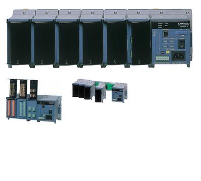
The MW100 is a scalable, high performance data acquisition and data-logging platform designed for standalone, networked, or PC-based operation under industrial operating conditions. It supports remote web-based configuration and monitoring. With its DIN rail design, it is often mounted in an enclosure or cabinet.
Description:
Industrial processes often employ multiple data acquisition systems to monitor the health of assets and facility infrastructure. These systems can be either standalone or built as nodes within a larger automation topology.
The MW100 is a scalable, high performance data acquisition and data-logging platform designed for standalone, networked, or PC-based operation under industrial operating conditions. It supports remote web-based configuration and monitoring. With its DIN rail design, it is often mounted in an enclosure or cabinet.
"Smart Logging" - Anytime, Anyplace
The MW100 is a scalable, high performance data acquisition/data-logging platform designed for both PC-controlled and stand-alone operation under harsh operating conditions. Open Ethernet connectivity with web-based configuration and data monitoring functions allow MW100 to handle a wide range of monitoring and historical logging functions. See real time trends with your web browser from any PC and no special software. A full range of input/output modules handle all of your process inputs with fast measurement speed and high noise immunity for rock-solid performance.

Anytime, Anyplace...
In a wide range of temperatures: -20 to 60° 1,2,3,4
Reinforced insulation: Between input terminal and case5 3700 Vrms (one minute) or 600 Vrms/VDC (continuous)
A wide variety of network functions: HTTP, FTP, DHCP, SNTP, E-mail, and others
Smart Logging...
High speed measurement with a single unit (10 channels/10 ms or 60 channels/100 ms):
Shortest measurement interval of 10 msMulti-interval: Enables mixing of three different measurement intervals in a single unit (measurement intervals can be set for each module)
Supports CompactFlash (CF) cards 6 of up to 2 GB Continuous data acquisition is possible on 60 channels at 100 ms for approximately ten days with a 2-GB card, or for three months on 60 channels at 1 s.
MATH function on the main module available with the /M1 option.
Collective data acquisition on 360 channels (via Modbus with the /M1 option)
The operating temperature range for the input modules and main module. The operating temperature range of the output modules is -20 to 50°.
Note that the power cord supplied with the main module differs depending on the operating temperature range (see the specifications on page 7). If the operating temperature range specification of the supplied standard power cord does not meet your requirements, we recommend that you select a screw-type terminal rather than the plug type for the main module power inlet, and supply your own power input cable.
The operating temperature range of the AC adapter used with DC power supplies is 0 to 40°.
Please consult with a representative for applications involving temperatures below -20°.
The withstand voltage value with the MX110 input module. For the withstand voltage values of other input and output modules, please refer to the specifications for those modules (GS 04M10B01-01E).
CF card not included (sold separately).
A custom MW100 measuring system is comprised of three elements; the MW100 main module, MX Series input/output modules, and MX150 Series base plate. The system can be bench mounted as-is or DIN rail mounted for rack or panel installations. A DIN rail-mounting bracket is included with the MX150.
The input/output modules, base plate, and accessories are all the same as those for the MX100 DAQMASTER series (AC adapter is for the MW100 only).
Input Modules

| Name | Model | Number of channels | Shortest measurement interval | Description |
|---|---|---|---|---|
10 channel pulse input module  | MX114-PLS-M10 | 10 | 100 ms | Non-voltage contact /Open collector (10,000 sample/sec integration speed) |
| 30 ch general purpose input module with 500 ms scan speed | MX110-VTDL30 | 30 | 500 ms | Clamp terminal, DCV/TC/DI |
| MX110-VTDL30/H3 | 30 | 500 ms | M3 screw terminal, DCV/TC/DI |

| Name | Model | Number of channels | Shortest measurement interval | Description |
|---|---|---|---|---|
| Universal Input Modules | MX110-UNV-H04 | 4 | 10 ms | DC voltage, thermocouple, 3-wire RTD, DI (non-voltage contact, Level (5 V logic)). Mixed input allowed. |
| MX110-UNV-M10 | 10 | 100 ms | DC voltage, thermocouple, 3-wire RTD, DI (non-voltage contact, Level (5 V logic)). Mixed input allowed. | |
| 4-Wire RTD and Resistance Input Module | MX110-V4R-M06 | 6 | 100 ms | DC voltage, 4-wire RTD, 4-wire resistance, DI (non-voltage contact, Level (5 V logic)). Mixed input allowed. |
| Strain Input Modules | MX112-B12-M04 | 4 | 100 ms | Built-in bridge resistance of 120 ohm |
| MX112-B35-M04 | Built-in bridge resistance of 350 ohm | |||
| MX112-NDI-M04 | For connection with an external bridge head and strain gauge type sensor (NDIS connector)) | |||
| 5 V Digital Input Module | MX115-D05-H10 | 10 | 10 ms | Non-voltage contact, open collector, and Level (5 V logic). Mixed input allowed. |
| 24 V Digital Input Module | MX115-D24-H10 | 10 | 10 ms | Level (24 V logic), Vth = 12 V |
Output Modules

| Name | Model | Number of channels | Ouput update interval | Description |
|---|---|---|---|---|
| Analog Output Module | MX120-VAO-M08 | 8 | 100 ms | Allows mixed voltage (±10 V) and current (4-20 mA) output |
| PWM Output Module | MX120-PWM-M08 | 8 | 100 ms | Pulse width modulation output module |
| Digital Output Module | MX125-MKC-M10 | 10 | 100 ms | "A" contact (SPST) |
Base Plate

Base plates available for all configurations, from 1 to 6 input/output modules.
When used for the MW100/MX100, you must replace the attachment with the one that comes standard with the MW100/MX100.
Accessories
 Connector Covers
Connector covers for open slots
AC Adapter (772075)
AC adapter for the DC power model.
Operating temperature range: 0 to 40°
*Only for the MW100
Accessories (Removable Terminal)

All input/output terminals are removable except for those of the MX112-NDI-M04. If multiple terminals are prepared ahead of time, no re-wiring is needed between measurements.

| Model | Description |
|---|---|
| 772061 | Screw (M4) terminal block (RJC (reference junction compensation) included). For use in combination with 772062. Compatible with MX110-UNV-M10, MX115-D05-H10, and MX115-D24-H10. |
| 772062 | Connection cable between input modules and the screw terminal block. Compatible with MX110-UNV-M10, MX115-D05-H10, and MX115-D24-H10. |
| 772063 | Plate with clamp terminals (RJC included). Compatible with MX110-UNV-M10, MX115-D05-H10, and MX115-D24-H10. |
| 772064 | Clamp terminals. Compatible with MX110-UNV-H04. |
| 772065 | Clamp terminals. Compatible with MX120-VAO-M08, MX120-PWM-M08, and MX125-MKC-M10. |
| 772067 | Plate with clamp terminals. Compatible with MX110-V4R-M06. |
| 772068 | Plate with clamp terminals (Built-in bridge resistance of 120 ohm). Compatible with MX112-Bxx-M04. |
| 772069 | Plate with clamp terminals (Built-in bridge resistance of 350 ohm). Compatible with MX112-Bxx-M04. |
| 772080 | Plate with screw (M3) terminal (RJC included). Compatible with MX110-UNV-M10, MX115-D05-H10, and MX115-D24-H10. |
| 772081 | Plate with clamp terminal for current with 10 ohm built in bridge resistance, applies to MX110-UNV-M10 |
| 772082 | Plate with clamp terminal for current with 100 ohm built in bridge resistance, applies to MX110-UNV-M10 |
| 772083 | Plate with clamp terminal for current with 250 ohm built in bridge resistance, applies to MX110-UNV-M10 |
The MW100 can be connected to multiple PCs at the same time. This allows monitoring and sharing of measured data by multiple users. A login function is included to enable assigning of access rights.
Measurement information shared

Measured data shared

Acquire up to 360 Channels in One System
 A large data acquisition system of up to 360 channels can be assembled using multiple MW100s and standard MODBUS TCP Ethernet communications. When equipped with the /M1 math option, the MW100 can acquire up to 300 channels of external data from additional MW100 units or other devices such as a PLC using MODBUS TCP communications. This provides a total system capacity of 360 channels (60 built-in measure channels + 300 external).
Serial MODBUS RTU communications (RS- 232 or RS-422A/485) can be ordered as a separate option with the same capability.
Connect to Other Devices

An optional serial MODBUS RTU interface provides data exchange functions with other devices such as recorders, PLCs and controllers. In this mode, MW100 can serve as expansion I/O or as a data acquisition terminal for another connected device.
Remote Data Acquisition
 When the measurement location is located remotely from the data monitoring station, a dial up phone connection can be used for communications. All MW100 web browser-based data monitoring and FTP functions can be used via this connection for remote data acquisition applications.
Screen updating may be slower depending on the communication environment.
Time Synchronization
 The MW100 can synchronize its clock to a network time-server using SNTP (Simple Network Time Protocol), allowing any number of MW100s in a system to have precisely matched time.
Both SNTP Server and Client modes are supported. In Server mode, one MW100 can acquire time data from a server using Client mode. It can then serve time data in Server mode to other MW100s that function as Clients.
Clock synchronization functions are allowed only when the measurement interval within the unit is two seconds or longer.
Select a CF card appropriate for the required data recording time. See the table below for the approximate time's worth of data that can be recorded for each size of card. For example, when recording ten channels of data at a 10 ms measurement interval, the approximate amount of data that can be recorded to a 128-MB CF card is 8.8 hours worth. On the MW100, measured data is recorded to the CF card via an SRAM. The SRAM is backed up with a battery (for approximately ten years), ensuring that even in the event of a power failure, data prior to the failure is not lost.
| Recording channels | Measurement interval | 128 M | 512 M | 1 G |
|---|---|---|---|---|
| 10 ch | 10 ms1 | Approx. 8.8 hours | Approx. 1.4 days | Approx. 2.8 days |
| 100 ms | Approx. 3.7 days | Approx. 14.8 days | Approx. 28.9 days | |
| 500 ms | Approx. 18.5 days | Approx. 74.0 days | Approx. 144 days | |
| 1 s | Approx. 37.0 days | Approx. 148 days | Approx. 289 days | |
| 2 s | Approx. 74.0 days | Approx. 296 days | Approx. 578 days (Approx. 1.5 years) | |
| 5 s | Approx. 185 days | Approx. 740 days | Approx. 1446 days (Approx. 3.9 years) | |
| 20 ch | 50 ms2 | Approx. 22.2 hours | Approx. 3.7 days | Approx. 7.2 days |
| 100 ms | Approx. 1.8 days | Approx. 7.4 days | Approx. 14.4 days | |
| 500 ms | Approx. 9.2 days | Approx. 37.0 days | Approx. 72.3 days | |
| 1 s | Approx. 18.5 days | Approx. 74.0 days | Approx. 144 days | |
| 2 s | Approx. 37.0 days | Approx. 148 days | Approx. 289 days | |
| 5 s | Approx. 92.5 days | Approx. 370 days (Approx. 1 year) | Approx. 723 days (Approx. 1.9 years) | |
| 60 ch | 100 ms | Approx. 14.8 hours | Approx. 2.4 days | Approx. 4.8 days |
| 500 ms | Approx. 3.0 days | Approx. 12.3 days | Approx. 24.1 days | |
| 1 s | Approx. 6.1 days | Approx. 24.6 days | Approx. 48.2 days | |
| 2 s | Approx. 12.3 days | Approx. 49.3 days | Approx. 96.4 days | |
| 5 s | Approx. 30.8 days | Approx. 123 days | Approx. 241 days |
Storage capacity in terms of time by CF card size and numbers of channels
At a measurement interval of 10 ms, the maximum number of channels that can be measured is 10. Eleven or more channels cannot be measured at a measurement interval of 10 ms.
At a measurement interval of 50 ms, the maximum number of channels that can be measured is 30. Thirty-one or more channels cannot be measured at a measurement interval of 50 ms.
Multi-Interval

The MW100 enables mixing of three different measurement intervals in a single unit. Measurement intervals can be set for each individual module. This allows you to measure various items under test at the most appropriate measurement intervals. Also, you can set data recording conditions1 for each measurement interval, thereby using the available space on the CF card as efficiently as possible.
Single: Save a file up to the specified size then stop recording. Full Stop: Stop recording once the CF card is full. Rotate: When the capacity of the CF card has been exceeded, the oldest files are deleted to free up space, then recording continues.
Trigger and Data Thinning Functions

Data Recording Using the Trigger and Data Thinning Functions
The MW100 is equipped with built-in trigger functions. Data recording can be started based on alarm values, time, external contact input, or other parameters. Once recording is started, it can be set to progress continuously or according to a specified data length. When specifying a data length, a pre-trigger can also be set. The MW100 also provides a data thinning function.
Portions of measured data can be omitted at regular intervals during measurement (minimum of four seconds) before data is recorded. Using the trigger and data thinning functions together provides "coarse" recording of general data and "fine" recording of abnormal data.
Broken Line Chart Output (/M1 Option)

This function is included with the MATH (/M1) option. Patterns can be output from the analog output and PWM output modules (MX120) by inputting the coordinates of the pattern you wish to generate. In the pattern output shown in the figure below, points (X1,Y1) through (X10,Y10) are input in advance, and the output is generated accordingly.
Creates hourly, daily, weekly, and monthly reports synchronized to measurement start and stop. On mesurement stop action, a report file is saved to the MW100 CF media. A report status display is provided in the web browser monitor mode. Report data is saved to a text (.txt) file compatible with common software applications.
Up to 60 report channels reporting data from assigned measure or math channels
| Report channel data: | MIN, MAX, average, summation, and instantaneous values |
|---|---|
| Report channel data: | tabular digital data display and graph for totalizer data |
| File format: | .txt text file (tab delimited) |
| Report math interval: | up to 100 ms |
| Email messaging: | An email message is sent at the report creation time |
| File transfer: | the report file can be transferred to an FTP server at the report creation time |

Report logging display

Graph display of totalizer data

Use Excel or other applications to create custom reports from the report text file.
MW100 Automatic Assignment Function (/MC1 Option for the DXAdvanced DX2000)
The DX2000 can use MW100 system hardware as additional external input channels. They can automatically recognize MW100s on a network and perform automatic assignment of the MW100 input channels to build a large multi-point data acquisition system quickly and easily with no PC requirement. System requirements: /MC1 external input option and /M1 math option. See the product bulletins and general specifications for details.

*The firmware version of R2.22 or later is required for the MW100 to support the automatic assignment function.
Support for devices with the Ethernet-Serial Gateway Function
The MW100 can now have direct communication with instruments connected via a multidrop connection to the PR300. (client)
Added data types
INT16 (server/slave)
Bit (client/master)
Connectivity with upstream devices (CENTUM, etc.)
Network load can now be adjusted through frequent polling from upstream devices. (server)
Connection by the Ethernet-Serial Gateway function

Firmware R3.03 Functions
Lite Monitor: Enables monitoring with a digital display, even in environments with low transmission speeds.
Setting List: A list of settings that can be displayed in TXT (text) or "printable" format.
Bit output computation: Enables output of the value of specified bits (0/1) of reference channel data (positive integers expressed as bits).
Alarm DO output: Preset settings of Off, Open, and Close were added as operations upon stop or error.
Modbus Slave/Server Function:
Added a coil function for mapping data on communication input channels (C001 to C300).
Added input relays for measurement channels, computation channels, and the main unit operating status.
Added input registers for mapping main unit mode information.
Summer Time Setting: The starting and ending date/time for Summer time can be set.

Firmware R3.02 Functions
Standard Support for the EtherNet/IP Protocol
Advantages of EtherNet/IP Compatibility
Able to develop a highly flexible systems
By using Ethernet/IP in the standard interface, the most appropriate multivendor systems can be readily developed for users. In addition, instruments can be added or modified without any additional programming, thus improving efficiency.Improved trend analysis
By making it easier to install the MW100 Data Acquisition Unit in systems and thereby facilitating the chronological monitoring of equipment operating conditions and quality data, trends can be analyzed with higher precision.Transmission of vast amounts of data at high speeds over a wide area
Data can be regularly transmitted at high speeds to instruments distributed over a wide area.Easy maintenance over a network
With Ethernet, maintenance staff do not need to learn a dedicated protocol for each instrument, making it easier to control the network.
Note 1: You must install firmware R3.02 to use EtherNet/IP with the MW100.
Note 2: EtherNet/IP is an open industrial application layer protocol supported by ODVA (Open DeviceNet Vendor Association).
Addition of User Authorization to the SMTP Authorization Function
A user authorization feature has been added to the SMTP Authorization function. SMTP authorization (SMTP Service Extension Authentication: SMTP AUTH) means that verification is made when sending e-mails so that only successfully authorized users can send e-mail. This newly added authorization function serves to further strengthen security for sending of e-mails.
Browse:
On A:PC-Based MX100
Next:Modular GM10
